

How to Use a Thermal Evaporation System for Thin Film Deposition
- Preparation Work
- Substrate Preparation
- Evaporation Source Control
- Optimizing Deposition Parameters
- Environment and Safety
- Post-Processing and Inspection
I. Preparation Work
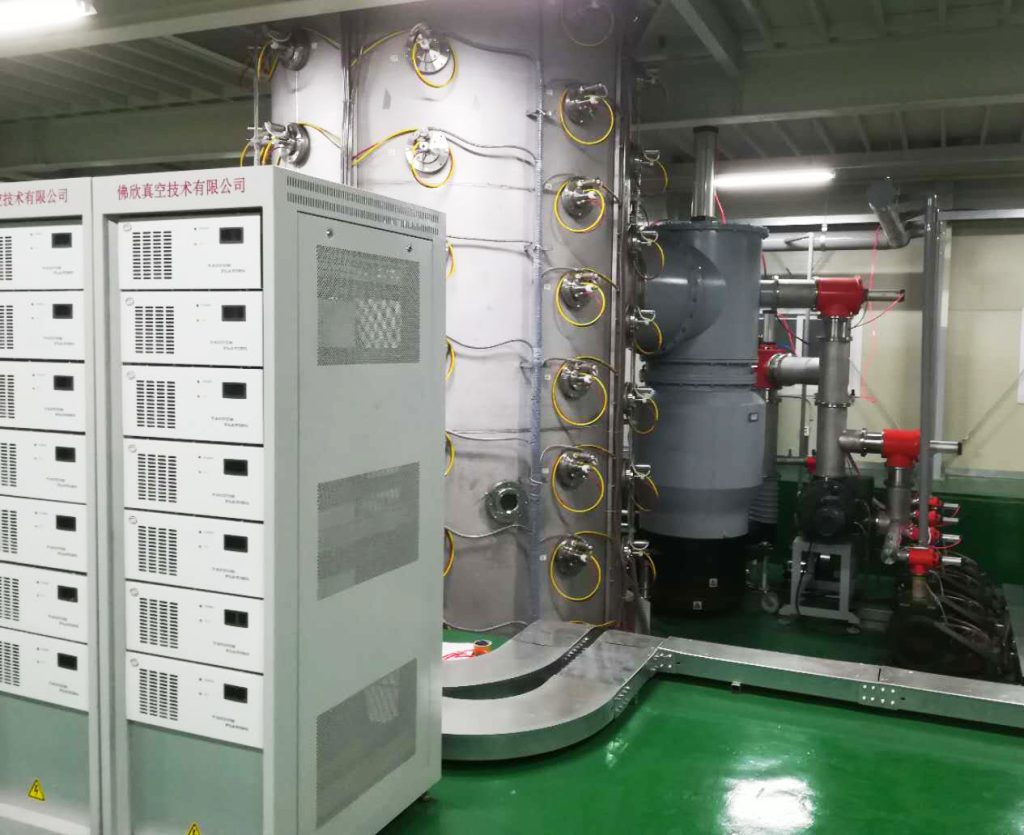
Cleaning the Vacuum Chamber
The vacuum chamber is the heart of your thermal evaporation system. Any tiny bit of contamination can ruin your thin film deposition. Grease, dust, or leftovers from past experiments can cause defects in your film. So, before you start, make sure the vacuum chamber is spotless.
- Use isopropyl alcohol or deionized water, along with a lint-free cloth, to carefully wipe the inner walls of the vacuum chamber to remove all visible stains.
- Check the o-ring for wear or stuck particles. If it’s damaged, swap it out right away to maintain a good vacuum for deposition.
- Run a blank cycle. Heat the vacuum chamber to 100-150°C for 30 minutes to remove the adsorbed water vapor or volatile pollutants.
- After the cleaning is completed, purge with high-purity nitrogen to ensure there is no residual solvent.
A clean PVD chamber can significantly improve the uniformity and adhesion of the thin film, laying the foundation for the subsequent thin film coating.
Checking the Vacuum System
Thermal evaporation deposition needs to be carried out in a high vacuum environment, usually requiring a pressure of 10⁻⁵ to 10⁻⁶ Torr. This ain’t something you get by just pumping the air out a few times. The system’s gotta be rock-solid.
- Check the vacuum pump. Make sure the oil level’s normal and the filter’s not clogged. If the pump’s maintenance log looks a bit dusty, deal with it now.
- Calibrate the vacuum gauge to ensure the pressure readings are spot-on. Wrong readings can screw up the thin film deposition quality.
- Fire up the vacuum system and see if it can stably hit 10⁻⁵ Torr within 30 minutes. If the pressure’s too high, grab a helium leak detector to check flanges or valves for leaks.
- Log the base pressure to make sure every experiment’s process is repeatable.
If the vacuum system keeps falling short of the target pressure, maybe the seals are shot or the pump’s losing efficiency. Figure it out fast, or the evaporation materials might oxidize, and the thin film deposition quality will take a hit.
Picking and Loading Evaporation Materials
The purity and loading method of evaporation materials directly affect thin film coating performance. Whether it’s aluminum, gold, or oxides, material purity typically needs to reach 99.99% or higher to reduce the influence of impurities on resistivity or optical properties.
- Select materials based on your goal: gold pvd coating works great for conductive layers, silicon dioxide (SiO₂) is ideal for optical coatings, and titanium nitride coating is good at the tribological coating.
- Pick the right crucible or evaporation boat. For example, aluminum pairs well with tungsten boats, while gold might need a ceramic crucible to avoid alloying.
- When loading, keep the material amount between one-third and one-half of the crucible’s capacity to prevent splashing from overfilling.
- Check the resistive heating filament or electron beam evaporation setup to ensure it can steadily heat to the material’s evaporation point.
After loading the materials, gently tap the crucible to ensure even distribution. Don’t forget to preheat the material in advance, which can reduce the splashing during deposition and make the thin film deposition smoother.
II. Substrate Preparation
Cleaning the Substrate
How clean the substrate surface is matters a lot for thin film deposition. It affects adhesion big time. Stuff like oil, dust, or organic residue can mess things up, causing defects or delamination. Here are two cleaning methods worth trying.
- Ultrasonic Cleaning: Place the substrate, like silicon wafer, glass, or metal, into an ultrasonic cleaning tank. Use a mix of isopropyl alcohol and deionized water as the solution. Set the frequency to 40-60 kHz and clean for 5-10 minutes. After cleaning, rinse with deionized water and dry with high-purity nitrogen gas to keep the surface clean.
- Plasma Cleaning: Put the substrate in a plasma cleaning machine. Use argon or oxygen plasma and run at 50-100 W power for 2-5 minutes. This removes organic contaminants and activates the surface, boosting surface energy. It helps the thin film stick better during pvd coating.
Once cleaned, use cleanroom gloves or tweezers to handle the substrate. You don’t want skin oils messing it up.
Substrate Heating
Substrate heating plays two key roles: it removes residual moisture and volatile contaminants, and it boosts the adhesion of evaporated materials to the substrate in PVD coating. This is critical for thin film semiconductors or optical thin films.
- Set Temperature: Pick a preheat temperature based on the substrate material. Glass or silicon wafers typically require 150-200°C, while metal substrates may need 200-300°C. Refer to the thermal performance of the substrate to avoid damage caused by overheating.
- Slow Ramp-Up: Heat gradually at a rate of 5-10°C/ minute to prevent thermal shock from damaging the precision substrate (such as ceramics).
- Hold Steady: After reaching the target temperature, maintain for 10-20 minutes to ensure uniform heating of the substrate and discharge the adsorbed gas in vacuum coating.
Watch the vacuum level during heating. Keep it between 10⁻⁵ and 10⁻⁶ Torr for vacuum deposition. If the system has a load lock, use it to transfer substrates without breaking the vacuum.
III. Evaporation Source Control
Pick the Right Evaporation Source
PVD equipment typically use resistive heating or an electron beam evaporation as the evaporation source. Which one to choose depends on your material and process requirements.
- Resistive heating: This method heats a tungsten or molybdenum boat by passing electricity through it. It works well for low-melting-point metals like aluminum or silver. The PVD system is simple and easy to operate, making it ideal for labs or small-scale production. However, temperature control isn’t very precise, which can cause splashing.
- Electron beam: This uses an electron beam to precisely heat a crucible. It’s suitable for high-melting-point materials like titanium or oxides. The heating is uniform, making it great for complex compounds. But the equipment is complex and maintenance costs are higher, as seen in e beam deposition.
When choosing an evaporation source, check the compatibility of the material with the crucible. For example, gold might alloy with a tungsten boat, so a ceramic crucible with electron beam evaporation is better. Test the evaporation system’s stability to ensure the current or electron beam output is reliable.
Controlling the Evaporation Rate
Deposition rate is critical in thin film deposition. It directly affects film quality and uniformity. Typical target is 0.1 to 1 nm/s, depending on the application. For example, optical coating needs slower rates, around 0.1 to 0.3 nm/s. Conductive layers can handle faster rates.
- When starting heating, gradually increase power over 10-20 seconds to avoid sudden vaporization that could cause splashing.
- Use a power controller to adjust the current or electron beam intensity. Aluminum usually needs 200-300 W, while titanium might require 1-2 kW.
- Monitor the evaporation source’s condition. If the material starts “smoking” or ejecting particles, immediately lower the power and check if the crucible is overfilled.
Maintaining a stable rate requires careful operation. Experienced operators might judge evaporation uniformity by observing the glow inside the vacuum chamber, but beginners should rely on a crystal monitor.
Using a Crystal Monitor
A quartz crystal monitor is a key tool for thin film deposition. It tracks deposition rate and film thickness in real time, with precision down to the Ångström level.
- Mount the crystal monitor facing the evaporation source, but keep it clear of the deposition path.
- Calibrate the monitor by entering the material’s density and acoustic factor, like 19.32 g/cm³ for gold or 2.7 g/cm³ for aluminum.
- During deposition, maintain a rate between 0.1 and 1 nm/s. If the rate fluctuates, tweak the power or check vacuum pressure.
- Replace the crystal every 6 to 8 runs to ensure accurate measurements.
The crystal monitor can also be set to stop automatically, hitting precise target thicknesses, like a 100 nm conductive layer or a 500 nm optical coating.
IV. Optimizing Deposition Parameters
Real-Time Monitoring of the Deposition Process
The quartz crystal monitor is the key tool in thermal evaporation, giving real-time data on deposition rate and thin film thickness to ensure precision in thin film deposition.
- Calibrate the monitor by entering the material’s density and acoustic factor.
- During deposition, keep the rate between 0.1 and 1 nm/s (0.1 to 0.3 nm/s for optical coatings, 0.5 to 1 nm/s for conductive layers).
- Set the target thickness (like 100 nm or 500 nm) and turn on the auto-stop function.
- If the rate fluctuates, check the evaporation system or vacuum pressure.
Adjusting Substrate Distance
The source-to-substrate distance affects thin film uniformity a lot. It’s usually best to keep it between 10 and 30 cm.
- If the distance is too short, less than 10 cm, the film gets thick in the center and thin at the edges, making uniformity poor.
- If the distance is too long, more than 30 cm, the deposition rate slows down, and you waste a lot of material.
- If your vacuum chamber supports substrate rotation, set it to 1-5 rpm to improve thin film uniformity for pvd coating.
- Write down the distance used each time, like 15 cm or 20 cm, to make sure the process can be repeated.
Introducing Reactive Gas
For oxide or nitride thin films like silicon dioxide or titanium nitride, you need to introduce reactive gas like oxygen or nitrogen to form the desired chemical composition.
- Use a mass flow controller to precisely adjust gas flow, typically between 0.1 and 10 sccm.
- Keep partial pressure between 10⁻⁴ and 10⁻³ Torr to avoid affecting the vacuum or causing insufficient reaction.
- Before deposition, let the gas flow for 1-2 minutes to stabilize the vapor deposition process.
V. Environment and Safety
Maintaining Vacuum and Cooling Systems
A high vacuum environment and a reliable cooling system are critical for thin film deposition.
- Use a helium leak detector to check the vacuum chamber’s seal, ensuring pressure stays between 10⁻⁵ and 10⁻⁶ Torr.
- Run the cooling water circulation, keeping water temperature at 20-25°C and flow rate at 1-2 L/min. Clean filters regularly to prevent scale buildup affecting the vacuum coating system’s efficiency.
- Monitor the vacuum pump’s condition to avoid overheating or leaks.
Wearing Protective Gear
Thermal evaporation deposition involves high temperatures and potential radiation risks, especially with e beam evaporation, where X-rays can be a hazard.
- Wear high-temperature gloves and safety goggles to protect against crucible splashes or high-temperature radiation harming your eyes.
- When using e beam evaporation, wear a radiation-resistant vest and ensure the equipment has lead shielding.
- Keep the lab well-ventilated to prevent buildup of volatile gases from evaporation materials during PVD deposition.
Cooling After Deposition
- Turn off the evaporation source power and let the crucible cool to below 100°C. This usually takes 20-30 minutes.
- Slowly introduce high-purity nitrogen gas at a rate of 0.1-0.5 Torr/min to gradually return to atmospheric pressure.
- Remove the sample after the substrate temperature drops below 50°C to avoid thermal shock from vacuum coating.
VI. Post-Processing and Inspection
Checking Thin Film Thickness and Uniformity
The thickness and uniformity of thin film deposition directly affect its performance, like conductivity, optical reflectivity, or wear resistance. Here are some tools to verify your results.
- Scanning Electron Microscope (SEM): Measures cross-sectional thickness (10 nm to a few microns) and checks surface features. Coat the sample with a thin layer of gold to boost conductivity. Magnify 1000-5000x for inspection. Keep thickness variation within ±5%.
- Atomic Force Microscope (AFM): Measures surface roughness (less than 2 nm). Scan a 1×1 µm² area. Great for checking nanoscale uniformity.
If the film’s uniformity is off, check the source-to-substrate distance or rotation speed. You might need to tweak it to 15-20 cm or 2-5 rpm.
Annealing Treatment
Thin films from vapor deposition coating often have internal stress or crystal defects that hurt performance. Annealing can improve crystal structure and boost film quality.
- Heat in a vacuum or inert gas like nitrogen or argon, at temperatures about one-third to one-half the material’s melting point (aluminum 200-300°C, gold 400-500°C).
- Control heating rate at 5-10°C per minute, hold for 30-60 minutes, then cool slowly at 2-5°C per minute.
- After annealing, use SEM or AFM to check again, looking at grain size and roughness for titanium nitride coating.
Application-Specific Testing
Different thin film coating applications need specific tests:
- Optical coating: Use a spectrophotometer to measure transmittance and reflectance, ensuring stable performance at target wavelengths.
- Wear-resistant coating: Measure hardness with a nanoindenter; titanium nitride coating should hit 20-30 GPa.
- Conductive layer: Use the four-probe method to check resistivity; gold PVD coating should be below 2.5×10⁻⁶ Ω·cm.