

Why Does PVD Titanium Coating Peel? Common Causes and Solutions
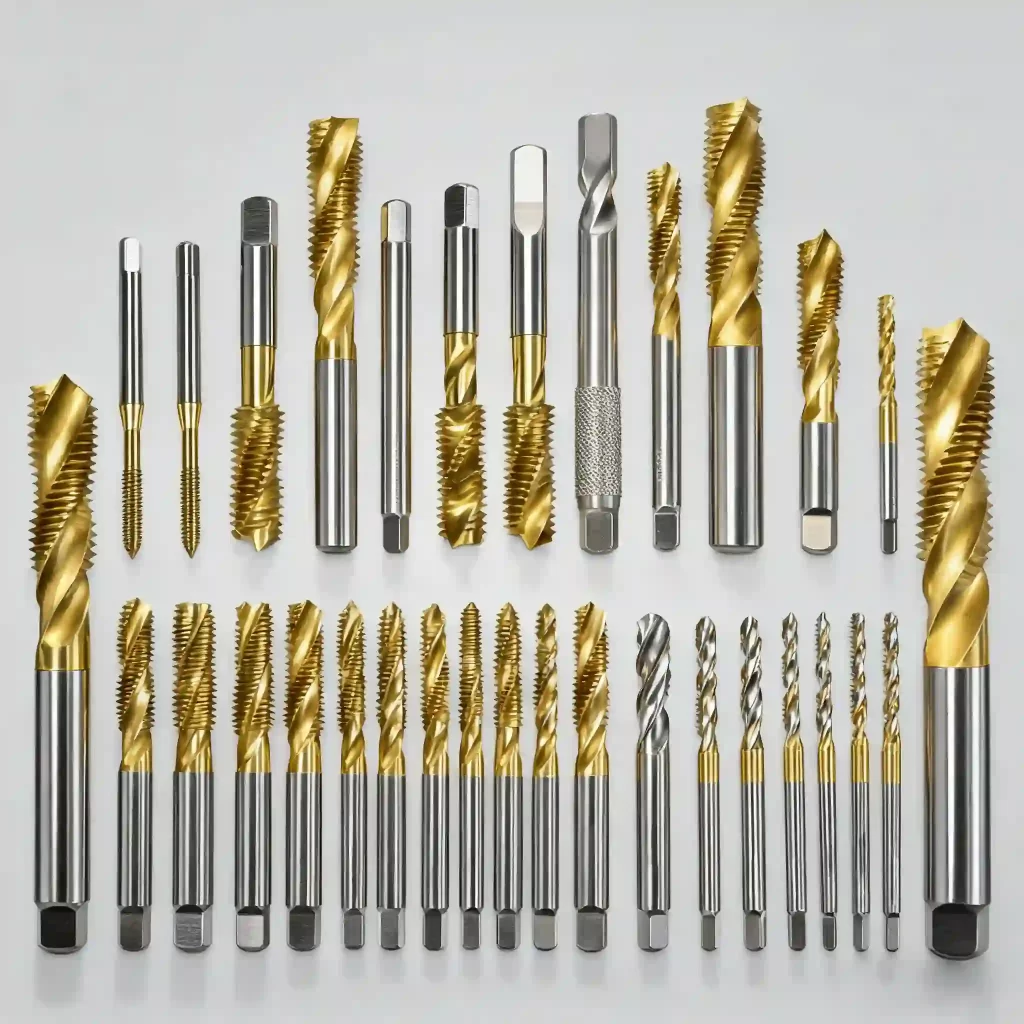
In the field of Physical Vapor Deposition, pvd titanium coating is widely used in cutting tools, molds, medical devices, and consumer electronics due to its excellent hardness, wear resistance, and decorative properties. However, coating peeling (Peeling/Delamination) is one of the most common and destructive failure modes in the production process. Many users searching for what is pvd coating often focus only on its advantages, overlooking the risks brought by improper process control. Peeling not only leads to direct product scrapping and increased rework costs but also seriously affects end-users’ trust in product lifespan.
Coating peeling is essentially a failure of interfacial bonding strength. Depending on the location of the failure, it can be classified as adhesive failure (separation between coating and substrate) or cohesive failure (fracture within the coating itself). In actual production, more than 90% of peeling problems do not stem from defects in the coating material itself but are caused by improper substrate pretreatment, deviations in process parameter matching, or unstable equipment status. Therefore, building a reliable adhesion system requires moving beyond focusing solely on the material itself and转向 systematic control of full-process variables. The performance of pvd titanium coating is essentially the result of the combined effects of substrate surface condition, vacuum coating process window, pvd equipment operating status, and inspection standards. In the pvd process, even a slight deviation in any link can form stress concentration or contamination layers at the interface. Next, we will break down these four key links one by one, analyze the specific mechanisms that may lead to interfacial failure, and provide optimization paths compliant with industry standards.
1. Substrate Factors: The Physicochemical Basis for Adhesion Formation
The substrate is the carrier for coating growth, and its surface condition directly determines the bonding strength during the initial stage of film nucleation. In vacuum coating processes, substrate preparation is often the first step that determines success or failure.
Surface Cleanliness: The Impact of Contaminants on Interfacial Bonding
Organic contaminants at the micro level (such as cutting fluids, polishing wax, fingerprint oils) will form a nanometer-level barrier film on the substrate surface, hindering the direct diffusion and bonding between titanium atoms and substrate metal atoms. Inorganic contaminants (such as oxide layers, rust) will lead to the formation of brittle oxide interlayers at the interface. For pvd coated stainless steel workpieces, if the passive film on the surface is not completely removed, it will directly lead to a decrease in bonding strength. Solution: A multi-level cleaning process must be established. The recommended process is: alkaline ultrasonic cleaning (remove grease) → acidic neutralization cleaning (remove oxides) → deionized water rinsing → vacuum drying. The key control point lies in the time management after cleaning. It is recommended to control the time interval from cleaning completion to furnace loading for coating within 4 hours to prevent the substrate surface from oxidizing again.
Surface Morphology: Roughness and Mechanical Anchoring Effect
Surface roughness (Ra) affects the mechanical biting force of the coating. If the Ra value is too low (<0.05μm), the surface is too smooth, lacking physical anchor points, and the bonding force is insufficient; if the Ra value is too high (>0.4μm), the coating is prone to stress concentration at microscopic peaks and valleys, triggering crack propagation. Recommended Parameters: For cemented carbide and mold steel, it is recommended to control Ra between 0.05-0.2μm; for stainless steel decorative parts, Ra can be relaxed to 0.1-0.3μm. For workpieces with high gloss requirements, precision sandblasting (alumina or glass beads) combined with polishing processes can be used to increase surface energy while controlling roughness. This is also a prerequisite for selecting suitable pvd coating materials for matching.
Substrate Material and Heat Treatment Status
The difference in the coefficient of thermal expansion (CTE) between different substrates is the main cause of thermal stress peeling. For example, the CTE of cemented carbide is about 5.0×10^-6/K, while the CTE of titanium nitride coating is about 9.0×10^-6/K. If the coating is too hard and too thick, the shrinkage stress generated during the cooling process exceeds the bonding force, which can lead to peeling. Optimization Suggestion: Before coating, the substrate needs to be stress-relief annealed. The temperature should be 30-50℃ lower than the substrate tempering temperature to release processing residual stresses. At the same time, follow the hardness gradient principle to avoid depositing overly hard coatings directly on soft substrates. For titanium coating applications, special attention needs to be paid to the matching of substrate hardness and coating hardness.
Substrate Preheating and Ion Etching Process
Preheating and degassing in the vacuum chamber are crucial. Moisture and gas adsorbed inside the substrate released at high temperatures will form “blistering” type peeling. It is recommended to set the preheating temperature at 200-350℃ and maintain it for more than 30 minutes. Ion Etching is a key step to activate the surface. Use high-purity argon (≥99.999%), apply a pulsed DC bias of -800V to -1200V, and bombard for 10-30 minutes. This process can remove the nanometer-level oxide layer, increase surface energy, and put the substrate surface in a high-energy active state, which is conducive to subsequent coating nucleation. This is an indispensable part of the pvd process.
2. Process Parameters: Key Control Points in PVD Deposition Process
Small fluctuations in process parameters may change the microstructure and stress state of the coating. In the thin film deposition process, precise control is the core of ensuring quality.
Vacuum System Parameters: Base Vacuum and Dynamic Leak Rate
The base vacuum level determines the purity of the deposition environment. If the base vacuum is too high (e.g., >1×10^-2 Pa), residual oxygen and water vapor will participate in the reaction, forming a loose oxide layer at the interface, seriously weakening the bonding force. Standard Reference: For high adhesion applications, it is recommended that the base vacuum be ≤5×10^-3 Pa, preferably ≤1×10^-3 Pa. The dynamic leak rate should be controlled at ≤0.5 Pa·L/s. During the reaction deposition stage, the partial pressure ratio of Ar (working gas) and N2/C2H2 (reaction gas) needs to be precisely controlled. For example, when depositing the transition layer, Ar:N2 = 3:1 can be used to gradually transition to 1:1 to avoid structural mutations caused by sudden compound generation. This is also a key control point in the pvd coating titanium process.
Bias Voltage and Ion Energy Management
Bias voltage determines the ion energy bombarding the substrate. If the energy is too low (<-300V), ion mobility is insufficient, coating density is low, growing columnarly, and bonding force is weak; if the energy is too high (<-1500V), it will cause substrate overheating, enhanced reverse sputtering effects, and even introduce excessive internal stress. Recommended Strategy: Adopt a “gradient bias” process. Use high bias to activate the surface during the etching stage; use medium bias to grow the transition layer during the initial deposition stage; use stable bias during the functional layer deposition stage. Pulsed DC power supplies compared to traditional DC can effectively reduce arc discharge, reduce macro-particle generation, and improve film density.
Deposition Temperature and Thermal Stress Control
Deposition temperature affects the diffusion ability and crystalline morphology of atoms. The suitable window for most metal substrates is 300-500℃. If the temperature is too low, the coating bonding force is poor; if the temperature is too high, it may affect the substrate matrix hardness. Stress Buffer: To relieve thermal stress caused by CTE mismatch, a multi-layer structure should be designed. The first layer deposits a 50-200nm pure metal Ti layer, utilizing the high toughness of metal-metal bonding; the second layer adopts a gradient nitride layer (Ti→TiN); the third layer is the target functional layer. This multi-layer nanostructure can significantly improve overall toughness and adhesion by deflecting cracks at the interface. For titanium pvd coating, this structure design is particularly important.
Reaction Gas and Deposition Rate
The purity of the reaction gas directly affects the stoichiometry of the coating. If the nitrogen contains too much oxygen, the coating will oxidize, the color will darken, and the bonding force will decrease. A deposition rate that is too fast will lead to a loose coating, while too slow will affect production efficiency. It is generally recommended to control the deposition rate between 1-3 μm/h, depending on the performance configuration of the pvd equipment.
3. Equipment Status: The Impact of Hardware Conditions on Process Stability
The hardware status of the equipment is the physical basis for stable process reproduction. Whether it is a pvd coating machine or large-scale mass production equipment, maintenance is crucial.
Vacuum Chamber Cleanliness and Internal Wall Coating Management
As the number of coating cycles increases, accumulated coatings will deposit on the vacuum chamber walls and shields. If these hanging coatings peel off, they will become particle sources, falling on the workpiece surface to form defect points, which then become starting points for peeling. Maintenance Suggestion: Establish a regular sandblasting cleaning system and record the hanging coating thickness threshold. Cleaning must be performed when the hanging coating reaches a certain thickness (e.g., 10-20μm). At the same time, install quartz crystal film thickness monitors or optical monitoring systems to 实时 feedback deposition rate abnormalities.
Fixture Design and Workpiece Clamping Specifications
The reliability of conductive contact between the fixture and the workpiece directly affects the bias application effect. If the contact resistance is too large (>0.1Ω), it will cause the actual bias of the workpiece to be lower than the set value, resulting in insufficient bonding force. Design Points: The workpiece spacing should be ≥1.5 times the height of the workpiece to avoid shielding effects leading to uneven coating. Adopt a combination rotation system of revolution + rotation, control the speed at 2-8 rpm, ensure film thickness uniformity within ±5%, and reduce stress concentration peeling caused by uneven thickness.
Target Status and Power Supply Stability
Target purity should be ≥99.95%, and 99.99% is recommended for high adhesion applications. If the target surface becomes “poisoned” (over-compounded), it will lead to unstable arcs and produce macro-particles. Power Supply Requirements: The power supply ripple coefficient should be ≤5% to ensure arc stability. The gas delivery system needs to use high-precision mass flow controllers (MFC), with a calibration cycle recommended to be ≤6 months, to ensure gas mixing uniformity. In the magnetron sputtering process, target utilization rate and smoothness are even more critical indicators.
Equipment Type Selection
Different equipment types are suitable for different application scenarios. For example, multi-arc ion plating is suitable for high ionization rate requirements, while magnetron sputtering is suitable for occasions with high surface finish requirements. Choosing the appropriate pvd equipment is the hardware prerequisite for solving peeling problems.
4. Diagnostic Methods: Systematic Troubleshooting Process for Adhesion Failure
When peeling occurs, a scientific diagnostic process can quickly locate the root cause. Many customers care about does pvd coating wear off, but in fact, many times it is not wear, but early peeling.
Failure Mode Observation and Preliminary Judgment
First, perform macro observation: Is the peeling located at the edge, center, or hole position? Is it spot-like, flake-like, or net-like? Subsequently, use a Scanning Electron Microscope (SEM) to observe the peeling interface morphology. If the interface is smooth, it is mostly interfacial contamination; if the interface is rough and has substrate residue, it is mostly cohesive failure or the bonding force is acceptable but the stress is too large. Energy Dispersive Spectrometer (EDS) can detect whether there is enrichment of abnormal elements such as oxygen and carbon at the interface.
Standardized Adhesion Testing Methods
Quantitative testing is the core means of evaluating process stability.
- Scratch Test: According to ASTM C1624 / ISO 20502 standards. Use linearly increasing load (1-100 N), record critical loads Lc1 (initial crack) and Lc2 (peeling). For cutting tool coatings, it is recommended that Lc2≥30 N; for decorative coatings Lc2≥15 N.
- Tape Test: According to ASTM D3359 standards. Suitable for softer substrates with coating thickness ≥5μm. Rating 5B is optimal (no peeling), 3B or below requires immediate process adjustment.
- Rockwell Indentation: According to VDI 3198 standards. Use 150 kgf load indentation, observe crack morphology through an optical microscope. HF1-HF2 level is qualified, HF3-HF6 level indicates insufficient adhesion.
Process Parameter Backtracking and DOE Verification
Retrieve the process record curves for the batch and compare whether vacuum level, bias waveform, and gas flow are consistent with the standard process. Adopt Design of Experiments (DOE) methods, fix other parameters, verify suspected key factors one by one (such as etching time, bias value), find the optimal parameter combination, and establish a robust process window. This is particularly important for high-precision applications such as coating for cutting tool.
Application Scenario Differential Analysis
Different industries have different requirements for adhesion. For example, pvd coatings for medical device need to meet biocompatibility and cannot have any peeling risk, while decorative parts may focus more on color consistency. In nitride coating applications, test standards need to be adjusted according to specific working conditions.
5. Solutions and Preventive Measures: From Root Cause to System Optimization
Solving peeling problems cannot rely solely on 事后 remediation; a preventive system needs to be established. Many users when comparing pvd vs chrome plating often overlook the complexity of PVD process control.
Pretreatment Process Standardization
Establish standard operating procedures (SOP) for cleaning – drying – transfer – furnace loading, control environmental cleanliness (recommended ≤10,000 level clean room). Introduce online surface detection means, such as contact angle testing, to quantify cleaning effects. Implement substrate batch management, try to use the same material and same heat treatment status substrates in the same coating furnace batch to reduce variables.
Process Window Solidification and Process Monitoring
Implement statistical process control (SPC) on key process parameters. Set ±3σ control limits for vacuum level, bias, and gas flow, and alarm automatically once out of range. Establish a first-piece verification system, every batch first piece must undergo rapid adhesion testing. Any process parameter change requires small trial verification, adhesion testing, and customer confirmation before mass production.
Equipment Preventive Maintenance (PM) Plan
Develop a detailed equipment maintenance plan. The vacuum system needs regular maintenance of molecular pumps, replacement of sealing rings, and leak rate detection; the electrical system needs calibration of bias power supplies, inspection of cable insulation and grounding resistance; the gas system needs regular pipeline leak detection, MFC calibration, and filter replacement. The stable status of the pvd coating machine is the guarantee of yield rate.
Personnel Training and Knowledge Precipitation
Strengthen training for operators so that they understand the “parameter-performance” correlation mechanism and avoid empirical adjustments. Establish a typical failure case library, containing failure pictures, process parameter records, and final solutions, to achieve knowledge precipitation and cross-departmental sharing.
External Services and Cooperation
For complex process problems that cannot be solved internally, you can consider seeking professional pvd coating services support. External experts can often provide more objective process diagnosis and optimization suggestions.
Conclusion: Building a Stable PVD Titanium Coating Adhesion System
The adhesion of pvd titanium coating is not determined by a single factor, but is the result of the systematic collaboration of “substrate preparation – process control – equipment status – quality management system”. By deeply understanding the physicochemical mechanisms of interfacial bonding, strictly implementing standardized operating procedures, and using scientific data-driven detection methods, enterprises can minimize the risk of coating peeling. Shifting from “post-testing” to “process prevention” and building a robust process window is the core path to improving PVD coating yield and product competitiveness. Whether it is titanium coating or other vacuum coating technologies, this principle applies.