



Sputtering Process Equipment: Components and Functions
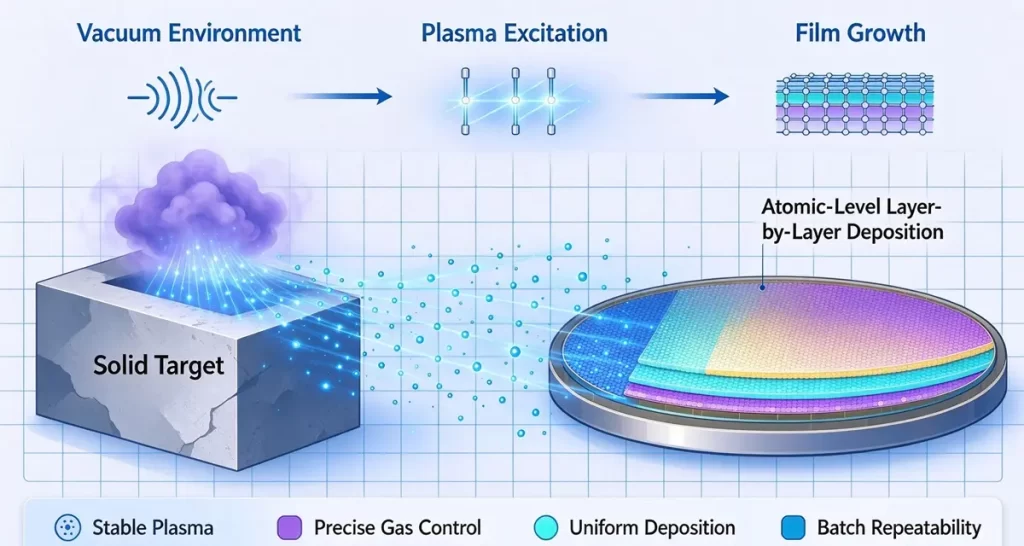
Sputtering process equipment is the vacuum system that turns a solid target into a thin film, one atom at a time. It combines a sealed chamber, a staged pumping system, magnetron cathodes, a matching power supply, precise gas control, and a rotating fixture that keeps the film even. Each part has a single job: hold the plasma steady and lay down a coating that is dense, uniform, and repeatable from batch to batch.
What Is Sputtering Process Equipment?
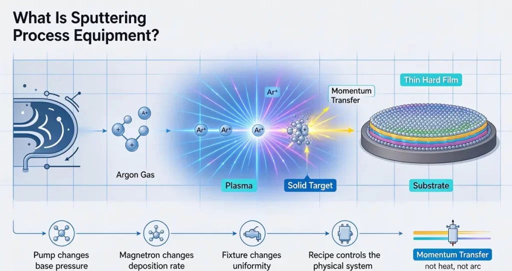
Sputtering process equipment is the hardware that performs sputter deposition inside a vacuum chamber. A working gas, almost always argon, is ionized into a plasma. Positively charged ions accelerate into a negatively charged target and knock atoms off its surface through momentum transfer. Those atoms cross the chamber and condense on the part as a thin, hard film.
A coating recipe is only a set of numbers. Sputtering process equipment is the physical system those numbers act on, and every component constrains the result. Change the pump and the base pressure and film purity shift. Change the magnetron and the deposition rate and target life shift. Change the fixture and the film uniformity shifts. That is why this guide works through each subsystem and the function it serves, then shows how to match a full system to your parts.
Sputtering belongs to the wider family of vacuum coating methods, and it obeys the same rules of vacuum technology as arc evaporation and thermal evaporation. What sets it apart is the release mechanism: momentum from ionized gas, not heat and not an electric arc.
How the Sputtering Process Works Inside the Chamber
The sputtering process runs in four physical steps, all of them inside a sealed chamber held at high vacuum.
- Evacuate. The pumping stack pulls the chamber down from atmosphere to a base pressure of about 10⁻⁴ to 10⁻⁵ Pa, clearing air and moisture that would otherwise contaminate the film.
- Dose the working gas. Argon flows in through a mass flow controller until the chamber reaches process pressure, typically 0.1 to 1 Pa. This is higher than arc evaporation or thermal evaporation uses, and for a clear reason: sputtering needs gas atoms present to form the plasma and carry momentum into the target.
- Ignite the plasma. Voltage across the target and chamber ionizes the argon. The ions strike the target and eject atoms from it. Nothing melts and nothing reacts chemically; the material leaves the target as a vapor by brute physical force.
- Transport and condense. The ejected atoms travel across the chamber and land on the substrate, building the film layer by layer.
Two settings govern most of the outcome. Process pressure controls how much residual gas scatters the sputtered atoms, which sets film density and purity. Deposition time, together with sputtering power, controls thickness. An operator tunes both against a coupon sample before a production run, then holds them fixed for the batch.
| Stage | What happens | Component doing the work |
|---|---|---|
| Evacuation | Chamber drops to base vacuum | Pumping stack |
| Gas dosing | Argon raises pressure to process level | Mass flow controller |
| Plasma ignition | Argon ionizes, ions strike the target | Power supply + magnetron |
| Deposition | Atoms land and build the film | Target + substrate fixture |
Sputtering Process Equipment Components and Their Functions
A production sputtering system is built from a fixed set of subsystems. Each one is sized to the parts it will coat and the film it must produce.
| Component | Function | Why it decides the outcome |
|---|---|---|
| Vacuum chamber | Sealed vessel that holds the plasma and the parts | Chamber volume and geometry fix the largest part, the batch size, and the pump load |
| Pumping stack | Reaches base vacuum and holds process pressure | Sets base pressure and pumping speed, which decide film purity and cycle time |
| Sputtering targets | Supply the coating material | Target purity and composition define the film’s chemistry, color, and wear performance |
| Magnetron assembly | Traps electrons to raise ionization | Magnetic field strength and shape set deposition rate, film uniformity, and target life |
| Power supply | Drives the plasma and the target | Its mode (DC, RF, pulsed DC, or HiPIMS) decides which materials and films you can run |
| Gas delivery | Meters argon and reactive gases | Precise argon and reactive gas flow controls pressure, film composition, and final color |
| Pressure control | Throttle valve and gauges hold setpoint | Holding the setpoint steady keeps deposition rate and thickness repeatable |
| Substrate fixture | Positions and rotates the parts | Rotation and geometry decide coating uniformity and how many parts fit in one batch |
| Cooling system | Removes heat from target and chamber | Removes heat from targets and chamber walls, preventing target damage and film defects |
| Control system | Runs the recipe and logs the data | Recipe storage and data logging keep every batch traceable and repeatable |
Sputtering Process Equipment Types: Our Five Series
Frame size matters as much as coating mode. A system built for eyeglass frames cannot coat a 2,500 × 3,000 mm stainless steel sheet, and a wide sheet line wastes capacity on small jewelry. Choosing the wrong platform is the most expensive mistake in a sputtering investment.
We build five platform families, each designed around a defined range of part geometry, coating mechanism, and batch volume.
| Series | Technology | Chamber / format | Typical parts | Application scenario | Coating focus | Product family |
|---|---|---|---|---|---|---|
| Multi-Arc | Cathodic arc + sputtering | Batch, multi-target | Door handles, sinks, hardware, jewelry | Kitchen and bathroom hardware, door and furniture fittings, high-volume decorative runs | Hard decorative films, gold tones | multi-arc ion plating |
| IP Magnetron | Magnetron sputtering | Batch, fine-film control | Watches, chains, small precision parts | Jewelry, watches, and eyewear that need a smooth, mirror-like, precious-metal finish | Smooth fine films, precious-metal look | magnetron sputtering system |
| GD Large | Multi-arc, large format | Large batch | Appliance and auto trim, large metal parts | Appliance and automotive trim, large hardware, and oversized parts run in large batches | Heavy-duty large-part coating | GD large multi-arc series |
| TG | Multi-arc with sheet handling | Inline / sheet | Stainless steel sheet, architectural panels | Architectural stainless steel panels and sheet or coil stock in continuous production | Continuous sheet and coil | TG sheet coating line |
| ZJ Large Diameter | Multi-arc for tubes | Long-axis | Long tubes, large-diameter cylinders | Long tubes, pipes, railings, and large-diameter cylinders | Tube and cylinder coating | ZJ large diameter line |
A platform is only half the decision. The other half is matching it to the exact part, which is why each series breaks down into task-specific machines.
| Machine type | Built for | Series |
|---|---|---|
| gold PVD coating equipment | Gold-tone jewelry and small components | IP Magnetron |
| jewelry plating machine | Rings, pendants, findings | IP Magnetron |
| watch IPG ion plating machine | Watch cases and bands | IP Magnetron |
| kitchen sink PVD coating machine | Stainless steel sinks | Multi-Arc |
| titanium door handle machine | Door handles and hardware | Multi-Arc |
| gold chain plating machine | Jewelry chains, high volume | Multi-Arc |
| stainless steel sheet PVD machine | Sheet and panel stock | GD Large |
| large hardware coating machine | Oversized metal parts | GD Large |
| ceramic tiles coating machine | Ceramic tiles and flat stock | TG |
| glasses frame coating equipment | Eyewear frames and small frames | Multi-Arc |
For lines that run magnetron mode, a dedicated magnetron sputtering vacuum coating machine is also available. What the film can look like once applied, from black DLC to mirror chrome, is set out in our guide to PVD coating colors.
The sections below take the four subsystems that most often decide whether a sputtering line meets its spec: targets and magnetrons, the power supply, the vacuum system, and the substrate fixture.
Sputtering Targets and Magnetron Cathodes
The target is the raw material of the film, and the magnetron is the engine that keeps it feeding.
Metal targets such as titanium, chromium, aluminum, copper, silver, gold, and zirconium sputter cleanly under direct current. Ceramic and oxide targets such as titanium dioxide, ITO, and silicon dioxide are electrically insulating and need a different drive. Either way, the target is bonded to a water-cooled backing plate so it survives continuous ion bombardment without cracking.
Behind the target sits the magnetron, a ring of permanent magnets that shapes a magnetic field over the target surface. That field traps electrons in a closed loop close to the target, extending their path and multiplying the collisions that create ions. The payoff is large: magnetron sputtering reaches useful deposition rates at lower pressure and lower voltage than plain diode sputtering. It is why nearly every modern sputtering system is a magnetron system. For the full mechanism, see how magnetron sputtering works.
One fact every buyer should know is target utilization. A planar magnetron erodes in a ring-shaped groove, the racetrack, and much of the target is never consumed. Typical planar utilization lands between 30 and 40 percent. Rotating cylindrical cathodes spread the erosion over the full surface and can push utilization past 70 percent, which cuts running cost on high-volume lines. The range of sputtering targets and how each behaves with different metals, alloys, and compounds is covered in two companion guides.
Power Supplies and Sputtering Modes
The power supply decides which targets you can run and which films you can make. Four modes cover almost every industrial sputtering line.
| Mode | Target type | Typical use | Notes |
|---|---|---|---|
| DC sputtering | Conductive metals | Cr, Ti, Cu, Ag, Au films | Simple, high rate, lowest cost |
| RF sputtering (13.56 MHz) | Insulating oxides and ceramics | TiO2, SiO2, ITO | Needs an impedance matching network |
| Pulsed DC / mid-frequency | Reactive metal targets | Oxides and nitrides from metal targets | Suppresses arcing and target poisoning |
| HiPIMS | Conductive targets | Dense, smooth, high-adhesion films | High ionization, lower deposition rate |
DC sputtering is the workhorse. It is cheap, stable, and fast, but it can only drive a conductive target, because positive charge would build up on an insulating target and kill the plasma. RF sputtering solves that by reversing polarity fast enough to neutralize the surface, at the cost of a matching network and lower efficiency. Pulsed DC sits in the middle and is the usual choice when a metal target reacts with oxygen or nitrogen to form a compound film.
HiPIMS pushes the idea further with very short, very high-power pulses. The vapor it produces is highly ionized, so the film lands denser, smoother, and better bonded than conventional sputtering, which matters for demanding optical and wear coatings. The trade-off is a lower deposition rate, so it is used where film quality beats throughput. For a closer look at the high-frequency end, see how RF sputtering is applied in production.
The Vacuum System: Pumps, Gauges, and Pressure Control
Vacuum quality is not a background detail. Sputtered atoms travel in a straight line only if the chamber is empty enough, so the vacuum system directly sets film purity and adhesion.
A typical pumping stack works in stages. A rotary-vane pump pulls rough vacuum from atmosphere. A roots blower boosts throughput in the middle range. A diffusion pump or a turbomolecular pump finishes the job and reaches the base pressure the process needs. Pressure is read across three ranges: a Pirani gauge for rough vacuum, a capacitance manometer for the process range, and a cold-cathode or ion gauge for high vacuum. A throttle valve holds process pressure steady by balancing gas flow against pumping speed.
Two engineering details separate a line that holds vacuum from one that fights leaks. The first is surface finish. On our chambers, main sealing surfaces are machined to Ra1.6 μm and secondary seals to Ra3.2 μm, with every internal vacuum surface polished to reduce outgassing. The second is sealing integrity. All vacuum welds follow pressure-vessel practice with no gas porosity, and leaks are located with an imported helium mass spectrometer rather than guessed at. The full range of coating machines we build follows these same standards.
Substrate Fixturing, Rotation, and Cooling
Uneven film thickness is the most common complaint on a new sputtering line, and the fixture is almost always the cause.
Thickness depends on how far each point on the part sits from the target and how long it faces it. A static part under a planar target will coat unevenly. Rotation evens the film out. Planetary fixturing, where parts spin on their own axis while the whole carrier turns, evens it further and lets one batch coat hundreds of small parts. Throw distance, the gap between target and substrate, sets both uniformity and rate: too close and the film runs hot and patchy, too far and the rate collapses.
Two more controls sit on the fixture. Substrate bias applies a small negative voltage to the parts, pulling ions in and densifying the growing film for better adhesion and hardness. Heating or cooling holds the parts at a temperature the process and the substrate can both tolerate. Before deposition, most cycles run a glow-discharge etch to strip the last layer of contamination and activate the surface so the film bonds at the atomic level.
Process Control, Monitoring, and Automation
A modern sputtering system is a computer-controlled process, not a set of hand valves.
A programmable controller runs a stored recipe from pump-down to vent. In-situ sensors close the loop. A quartz crystal microbalance measures deposition rate and thickness in real time, so the controller can stop the cycle at the target thickness. Optical emission spectroscopy watches the plasma and holds reactive gas flow steady, which is what keeps a nitride or oxide film from drifting in color or composition. Every run is logged, so any batch can be traced back to its exact parameters.
That traceability is what makes sputtering repeatable at scale. It is also what lets a recipe move from a sample coupon to full production without guesswork, and what a customer audit will ask to see.
How to Choose Sputtering Process Equipment for Your Parts
Sizing a system comes down to matching five requirements to a platform. Get these right and the line runs; get one wrong and it runs badly for years.
| Requirement | What it drives |
|---|---|
| Part size and batch volume | Chamber dimensions and pump capacity |
| Part geometry (flat vs. complex 3D) | Target layout, rotation, and whether arc mode is needed |
| Coating material | Target type and power supply mode (DC, RF, pulsed DC, HiPIMS) |
| Film spec (thickness, hardness, color) | Power, gas, bias, and cycle time |
| Substrate limits (heat, outgassing) | Deposition rate, throw distance, and fixture cooling |
Two rules of thumb save most of the pain. First, match the chamber to the largest part plus clearance, not to the average part; a machine that is slightly too small has no fix. Second, decide early whether the process is decorative or functional, because functional coatings such as wear or optical films usually need tighter thickness control and in-situ monitoring that a purely decorative line does not. If you are still comparing vendors, our notes on sputtering machine manufacturers cover what to check before you commit.
If any of this is unclear for your parts, the fastest path is a sample test. We run our own titanium coating plant, so a recipe can be proven on real parts before it goes into a machine spec.
How Much Does Sputtering Process Equipment Cost?
Price tracks chamber size, pump capacity, number of targets, and power supply mode, not the brand on the door. That makes a fair comparison hard unless you normalize the spec first.
The figures below are broad market references, not quotes: the exact number always depends on your parts and your recipe.
| System class | Typical parts | Rough market range (USD) |
|---|---|---|
| Small batch / R&D | Jewelry, watch parts, small precision components | 20,000 – 80,000 |
| Mid-size batch production | Hardware, sanitary ware, and mid-volume decorative parts | 100,000 – 400,000 |
| Large-format line | Architectural sheet, tube, and appliance or auto trim | 400,000 – 1,500,000+ |
Two adders move the number more than anything else. RF or HiPIMS power supplies cost more than DC, and in-situ thickness monitoring adds again, which functional coatings usually require. Chamber size is the biggest multiplier of all: doubling the chamber can more than double the price.
The number that matters is not the purchase price but the running cost per part. Target utilization, cycle time, and uptime decide that, and all three are engineering choices you can ask about before you buy. For current lead times and a configuration-based quote, see our PVD coating machine page or contact our engineers with your part and spec.
Related Equipment and Services
Sputtering is one mode inside a broader coating toolkit, and the choice often comes down to the part, not the process. Multi-arc ion plating lines cover complex 3D hardware, while magnetron systems cover smooth precision films, and the same parts can be PVD coated stainless steel when corrosion resistance is the priority.
To move from a spec sheet to a working line, send us a sample part. As a PVD coating equipment manufacturer with 27 years in vacuum coating, we will coat your part, test it against the eight acceptance items, and come back with a matched configuration rather than a catalog number. Start with a sample coating test, take a factory tour, see what we build across coating applications, read more about FOXIN, or talk to our engineers.
FAQ
What is sputtering process equipment?
Sputtering process equipment is the vacuum system that carries out sputter deposition. It includes the vacuum chamber, the pumping stack, the targets and magnetron cathodes, the power supply, the gas and pressure controls, the substrate fixture, and the control system that ties them together.
What is sputtering process equipment used for?
It is used to apply thin, hard films to parts. Typical work includes decorative gold and black finishes on jewelry and hardware, wear and corrosion layers on tools and fixtures, optical and insulating films on glass and ceramics, and conductive layers in electronics.
What pressure does sputtering run at?
A sputtering chamber is pumped to a base pressure of about 10⁻⁴ to 10⁻⁵ Pa, then argon is added to reach a process pressure of roughly 0.1 to 1 Pa. That working pressure is higher than arc or evaporation processes use, because the gas itself is what forms the plasma.
Can sputtering coat 3D parts?
Yes, but it depends on fixture design. Flat and gently curved parts coat easily, while complex 3D shapes need rotation, planetary fixturing, or a bias voltage to reach recessed surfaces. For parts with deep undercuts, arc evaporation often covers better than planar sputtering.
What is the difference between sputtering and arc evaporation?
Sputtering releases coating atoms by ion bombardment of a target, which gives smooth, dense, uniform films and works with insulating materials. Arc evaporation uses an electric arc that vaporizes the target, which gives a higher ionization rate and better coverage of complex shapes. Both are PVD vacuum processes, and both run in the same kind of chamber.
How much does sputtering process equipment cost?
Cost depends on chamber size, pump capacity, target count, and power supply mode rather than brand. As a market reference, small batch or R&D systems run roughly USD 20,000–80,000, mid-size batch production systems about USD 100,000–400,000, and large-format lines USD 400,000 and up. RF or HiPIMS power supplies add cost over DC. The running cost per part, driven by target utilization and uptime, usually matters more than the purchase price.